Atmospheric: a dual-sensor board featuring an STM32 MCU and SD card read and write functionality. It features two dual-sensors, one measuring absolute pressure and temperature, the other relative humidity and temperature. Based on these values, the MCU then calculates altitude.
Background
I wanted to make a board that not only would allow me to extend my knowledge of embedded programming, but also test my capabilities of board design due to its complexity compared to my previous projects. So I chose a project that required more thorough design verification and planning, and also required more precise assembly. My attempts to use hot-air guns on PCBs like this in the past have left me with poor results, so I put my recently built reflow oven to the test. This allowed me to get precise temperatures so that I didn’t melt plastic connectors, and so that I could achieve high-quality solder joints. I was also implementing data storage on my board, which was something I had never done before. For these reasons, I decided to design a board that would autonomously and continuously measure and record temperature, humidity, and pressure – nicknamed Atmospheric!
Design Constraints
I wanted the board to record accurate data, be portable, and require little upkeep. As such, it had to be:
- Small (less than 900 mm2)
- Long battery life (at least 24 hours)
- Accurate sensors: no more than ±0.5°C (temperature), ±3% (relative humidity)
- Onboard battery charging capabilities (under 2 hours charge time)
- Data logging (with microSD)
- Cost-effective
Component Selection
The Microcontroller
Selecting a μC from the STM32 series was a time-consuming process, in which I chose between μCs with different communication protocols for data logging (SPI vs SDIO vs SDMMC), IC packages (BGA vs UFQFPN), and the actual series (F series vs L series). In the end, I chose to use an STM32L4 series μC, with SPI to communicate with the microSD (μCs featuring SDIO are more expensive), a UFQFPN package (for easier soldering and relative cost-effectiveness), and the L4 series (due to remarkably low current consumption and relative price).
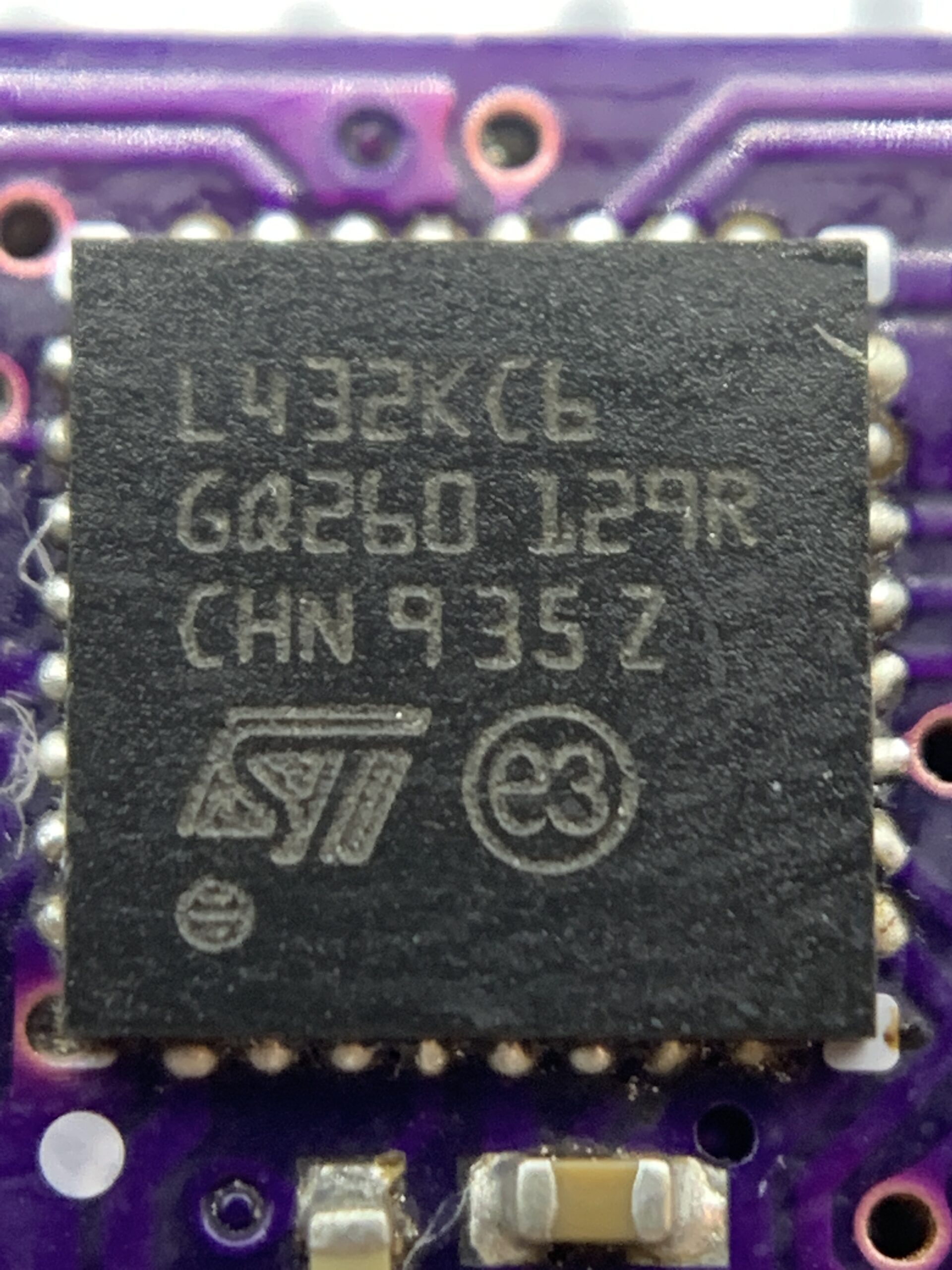 UFQFPN STM32
The Charger and Sensors
To achieve the charging capabilities I desired, I used a Texas Instruments Li-Ion charger and Power Path manager Integrated Circuit (IC). This IC is capable of charging a Li-Ion up to 0.5A, which was much higher than I required. However, my desired charging current of 0.1A was easily achieved by implementing a resistor with a calculated value. This resulted in sub-2-hour charge times. The Charging IC also allows for the board to be powered by USB when the battery is unplugged, due its power path features.
Finding accurate sensors was one of the easier tasks and again I chose a Texas Instruments device: a combined humidity and temperature sensor (HDC1080DMBR). This sensor boasts accuracies of ±2% Relative Humidity (RH) and ±0.2°C. Later in the project, I also chose another combined sensor, from TE Connectivity, which measures barometric pressure and temperature. The addition of a barometric pressure sensor was due to its minimal effect on quiescent current and free space on the PCB, but also for fun!
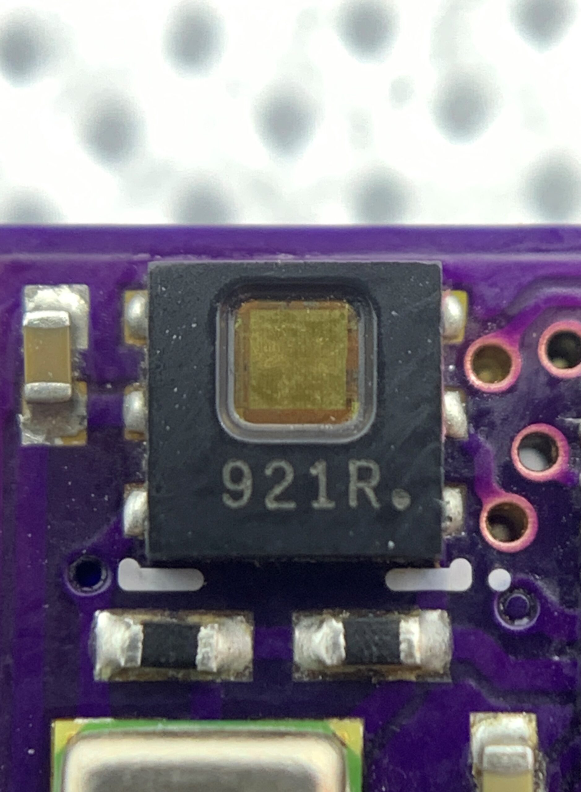 HDC1080DMBR sensor
Component Integration
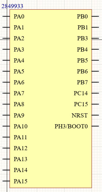
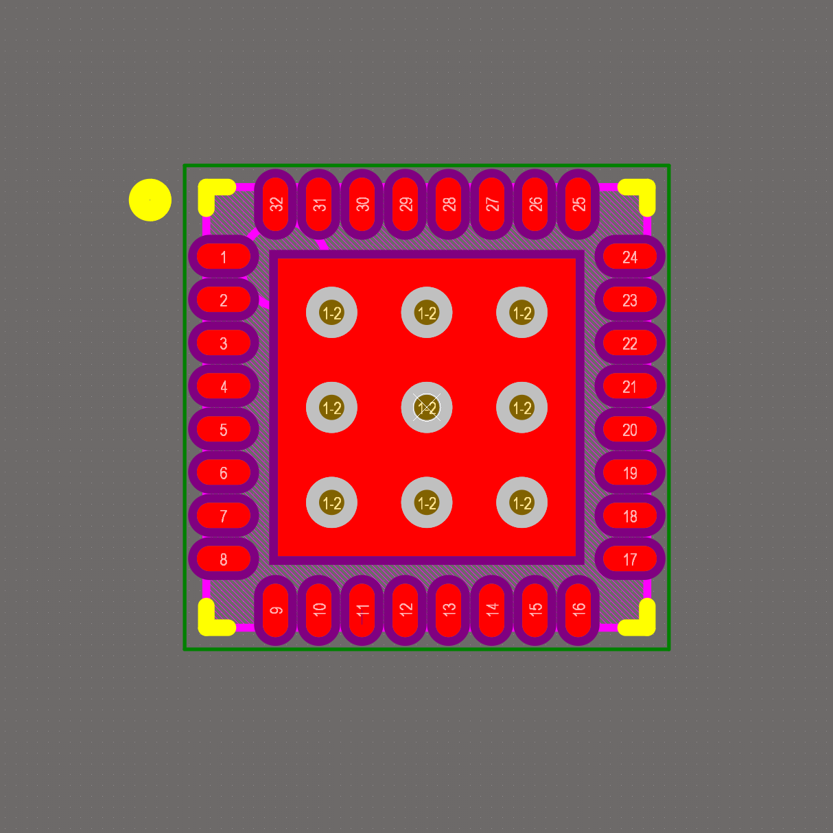
To integrate the components I had chosen into the board designer (Altium), I first had to generate the footprints and create the symbols. This had to be done for all components that were not already uploaded onto Altium’s database (the vast majority) or which were already uploaded but had insufficient quality. This phase of the board design is quite tedious and somewhat time-consuming. However, after it comes to the most interesting steps. See below for examples of what the footprint and symbol looked like for the STM32 MCU.
In part II of the blog, I will discuss Schematic design, PCB layout, and routing.