Atmospheric: a dual-sensor board featuring an STM32 MCU and SD card read and write functionality. In this post, I will talk about the physical testing of the board, programming, and issues I faced. Finally, I’ll outline ideas for improvement for future iterations, which I hope to detail in future blog posts.
Testing
When first testing the board, I realised there was an issue: the board didn’t work! I investigated by first probing the main power rail with my multimeter, where I measured a voltage around zero. This was odd, as it was supposed to be 3.3 V. The consequence of this was that the sensors, microcontroller, and SD card were left unpowered. I quickly realised the issue after additional voltage readings on different voltage lines, and it was a stupid one: I had mistakenly used the wrong version of a voltage detector chip… The one I was using outputted a low signal when the voltage was above a threshold, the opposite of what was required (a high signal)! The mistake simply stemmed from me buying the wrong version of a chip. As stupid as that sounds, I’m guessing it was because both versions only had a one-digit difference in their names.
The voltage detector’s role in the battery protection circuit is to turn the load switch on or off, depending on the voltage of the battery. During its intended operation, it should tell the load switch to cut the power to the sensors and microcontroller when the voltage falls below ~3 V, protecting the battery from deep-discharge. However, with the output signal being inverted on the sensor version I mistakenly had, it would instead turn the load switch on when the voltage was below 3 V. I’m sure you can tell that this was not the desired function. I luckily realised after some thinking that the fix was a simple one.
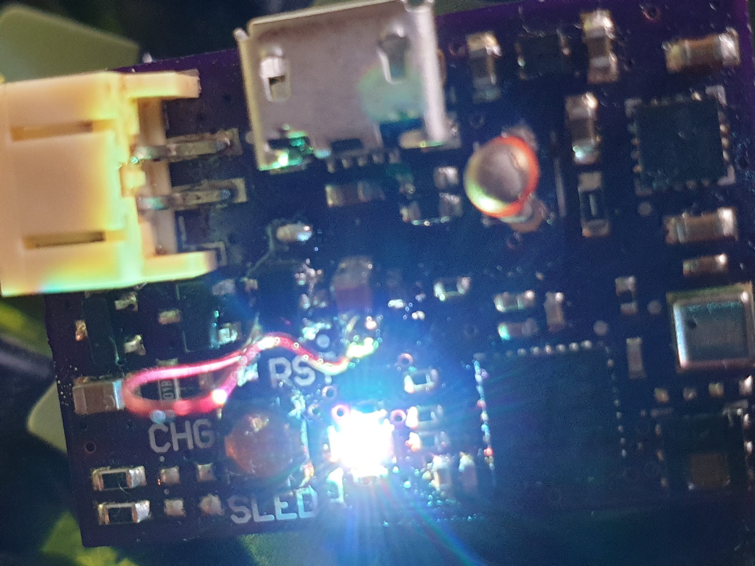
As you can see in the picture, the fix was to bypass the load switch with a piece of copper wire. This worked because now nothing was blocking the 3.3 V rail from being powered. The board functioned perfectly as soon as this was done! The RGB LED on the board lit up nice and bright, greeting me.
There was not much further testing that took place except general voltage readings with the multimeter. More insightful testing with my oscilloscope was very troublesome due to the difficulty of holding the probes in position. I really should have added holes for the probe hooks.
Programming
You may be rightly wondering; how do I program the board? You may remember that the USB connector shown in the schematic in one of the previous posts didn’t have the data lines connected. Instead, I designed my own interface to program the board through the use of a ribbon cable, connectors, and adapter board. I created and assembled the adapter board that connects to the STM board programmer, which allows for the ribbon cable connection. I chose this because the connector is super small. This is more understandable when viewing the pictures below.
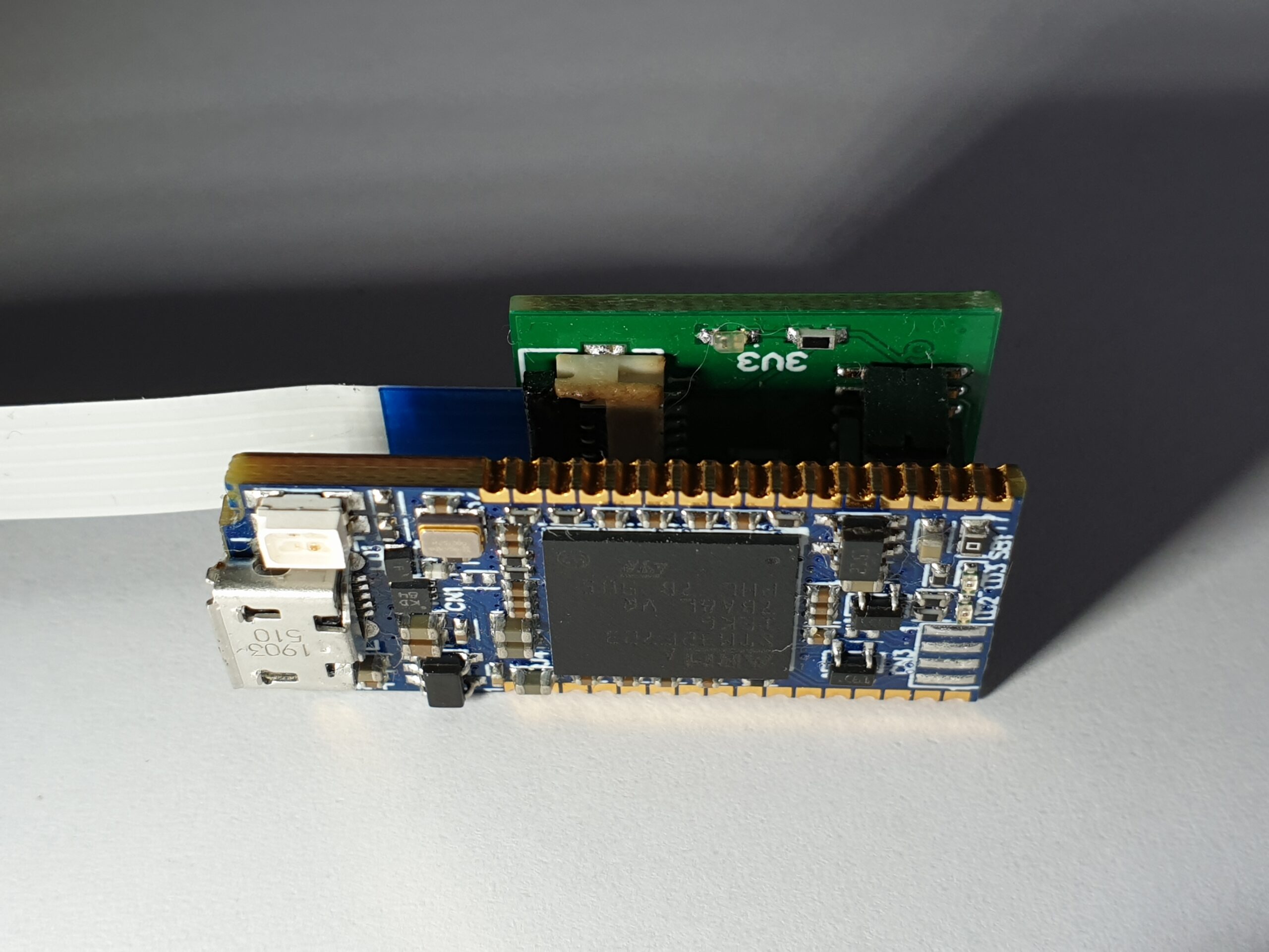
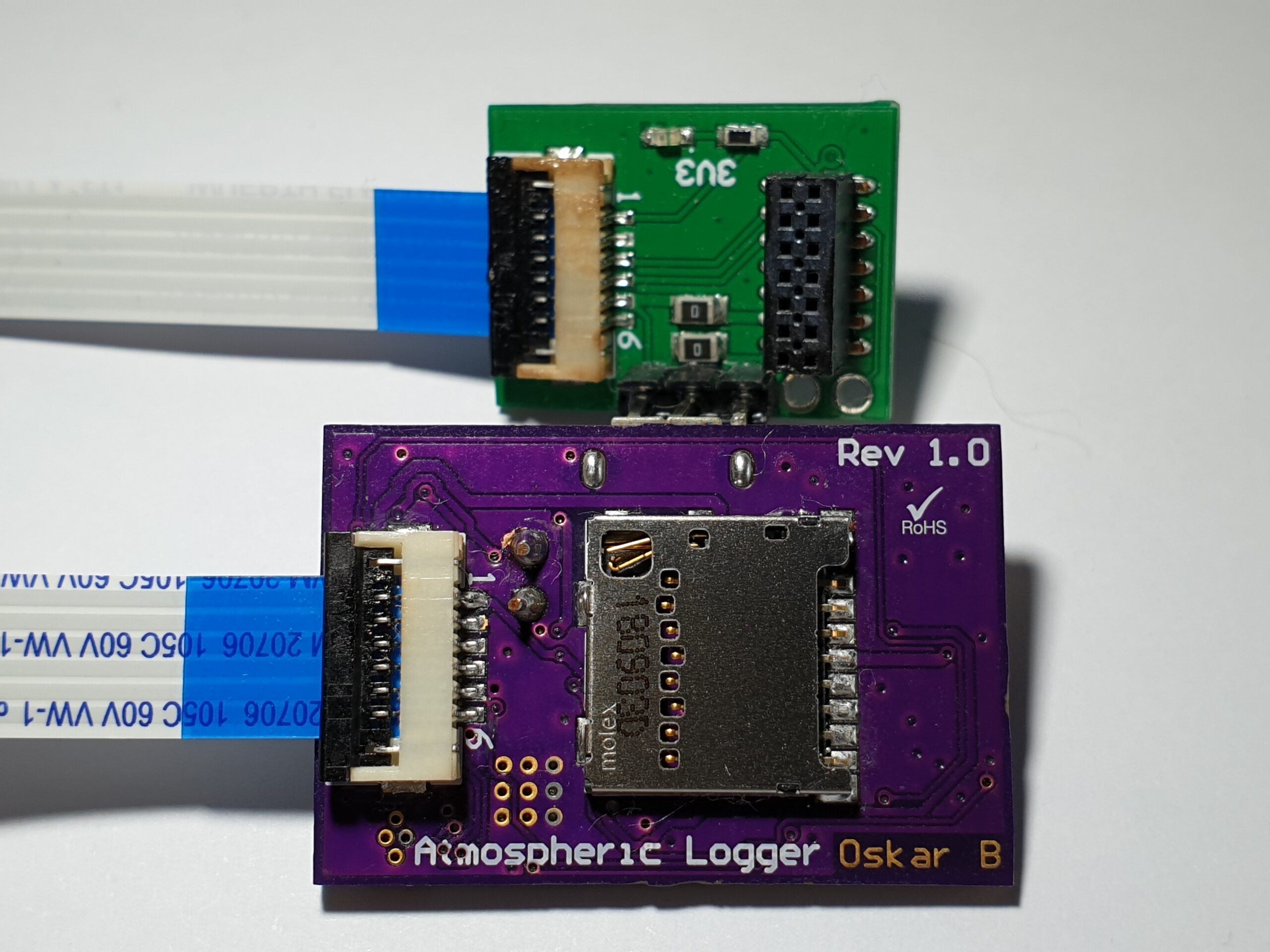
As you can see in the pictures, I horrifically melted the connector on the adapter board. That’s my own fault as I was using my hot air gun. Unfortunately, my reflow oven wasn’t around at the time of making it! The glistening blue board connected to the adapter is the STM programmer, which I connect to my computer over USB.
I was unsure when writing this blog about how much detail I should go into when discussing programming, and I concluded that a good overview would be suitable. The board is programmed in C, which is converted to Assembler – a very low-level language – by the software. C is a relatively new language to me, so I wasn’t speedy in any way when writing the code. I also used ST’s HAL library to make the code more universal across their microcontroller portfolio in case I switch microcontroller in future iterations.
There are three main aspects to the code: sensor communication, SD card communication, and sleep. The sensor communication is done through the I2C protocol and the SD card communication with the SPI interface. The SPI interface with the card was the most challenging part of programming, as this is not natively supported by the HAL library. Instead, I opted to use an open-source SPI SD Card driver. I could have tried to program it myself, but it would have delayed the overall project. It is something I can attempt in the future, though!
I am going to try to avoid going into too much detail about these two communication methods, as like many other things mentioned in this blog, they are complex and deserve their own post detailing their impressive uses. The SD Card driver, once installed, allowed me to use the native HAL commands to write data to the SD card. After this milestone was achieved, I started to get to work on the I2C communication code. I made my own functions in the code to get the pressure, humidity, and temperature from the two sensors. These functions are called once the MCU wakes up from its sleep, and the results are assigned to variables. These variables are formatted into a string, which is then written to the SD card. Once the writing was complete, the board put itself to sleep, reducing the quiescent (not active) current.
Results
This text file on the SD card could be viewed on a computer after data was gathered and the resulting data is shown below (when imported into Excel):
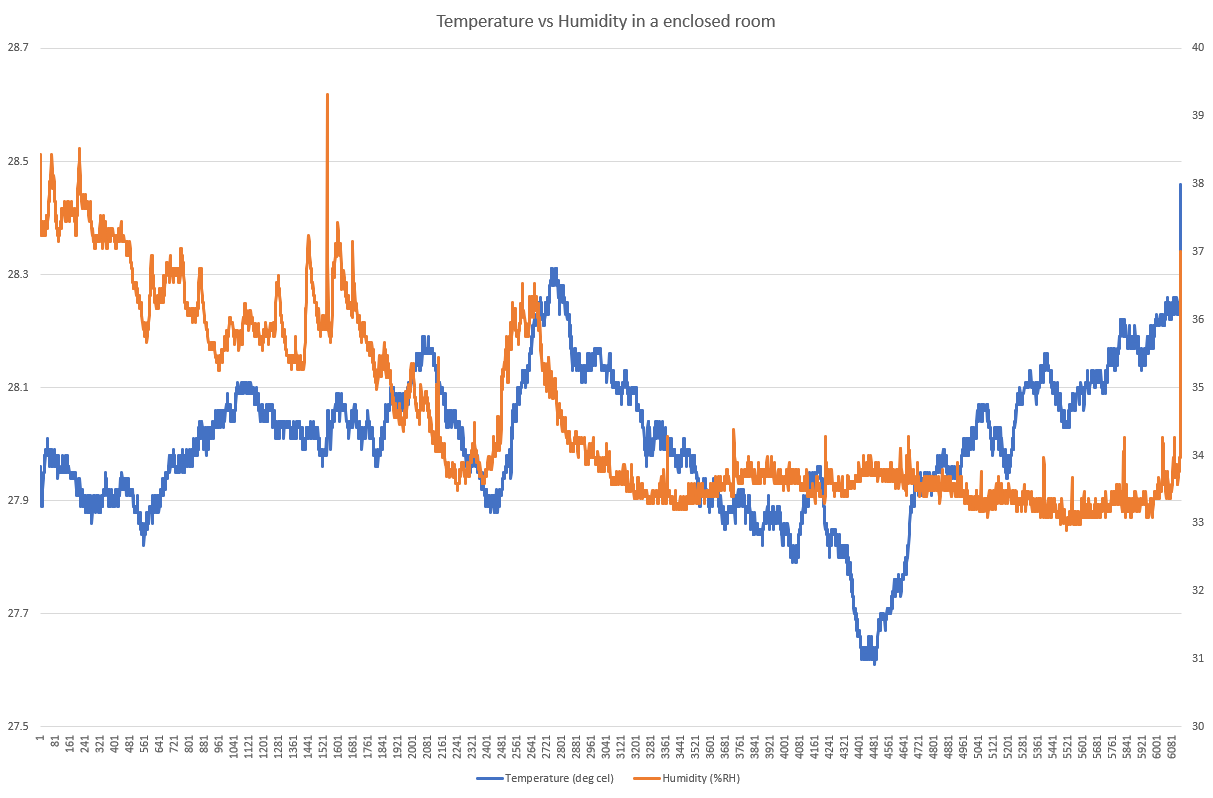
Humidity in orange (% Relative Humidity), and temperature in blue (degrees Celsius)
These results were from the temperature and humidity sensor (dual sensor in one package), which are factory calibrated. The calibration values are used in internal algorithms to get accurate temperature and humidity values. Unfortunately, the pressure & temperature sensor (another dual device) required the algorithms to be done on the microcontroller, which I found really annoying. This meant I had to retrieve the calibration values from the sensor’s memory and process the calibration equations.
Issues & future iterations
The version described in this blog definitely had its issues, which I have carefully thought about how to overcome in the next version. The first issue was a short battery life. This was because of the high quiescent current draw, from the amalgamation of a few bad choices, in hindsight.
Another issue was the lack of a timestamp for the data values. The times shown in the graph above was extrapolated, albeit somewhat accurately, from the start and stop times. For any really useful data logger, times of data measurements need to be known. This can be done using a device called a Real-Time Clock (RTC), which keeps track of a set time and date (some also feature alarms). RTCs are embedded into most microcontrollers, such as the one I use for Atmospheric. This means that I could simply just set the date and time once, and then poll the time value whenever I am writing the sensor values to the SD card.
The final major issue was the pressure & temperature sensor simply not producing accurate readings, based on an external calibrated thermometer. I am sceptical of the idea that it was my code that made the values volatile, but it is possible. Instead, I hypothesise that it was some flux (or maybe solder paste?) that entered the pressure sensor’s opening during reflow and caused its lack of functionality. I will probably never know (at least without taking the component apart!).
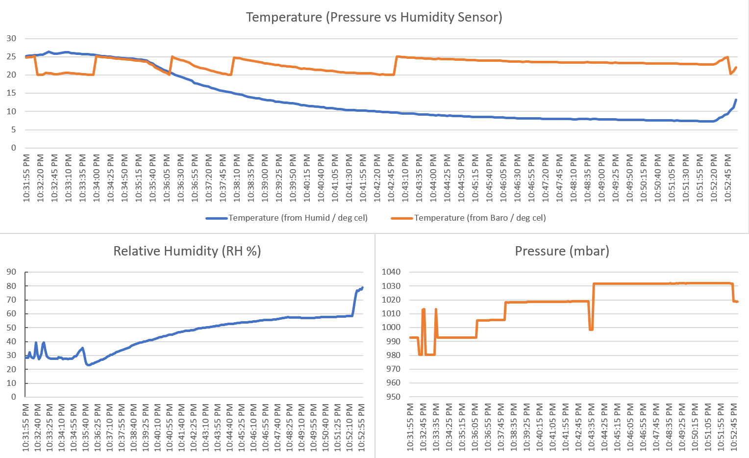
As you can see from the graphs above, the temperature values from the humidity & temperature sensor (blue in top graph) were perfectly accurate. However, the temperature values from the pressure & temperature sensor (orange in top graph) were chaotic, and not at all accurate (based on a calibrated external thermometer). Furthermore, the volatile pressure output from the pressure & temperature sensor (bottom right graph) was peculiar, and I don’t think any of the values that it measured were accurate.
The next version of this board, which I’ve named nanoAmp, addresses all of these issues and more. The battery life will be increased by using an energy harvesting battery charger, and a small solar panel (like the ones in calculators). A new pressure sensor will also be used, which features internal calibration algorithms. Alongside this, it will use new techniques to reduce the quiescent current draw, which is why it should have an enormous battery life (estimates are over a year). One of the factors that allow for this is the use of a different load switching mechanism… I don’t want to spoil it all now!
I hope you enjoyed reading through this multi-part story as much as I enjoyed writing it. I can’t wait to show you all the next version of Atmospheric!