Hello!
In this part of the series, the focus will be on the principle of current measurements, how I plan to measure it on the board, and voltage measurements.
The theory of current measurements
The board will measure the current consumption of the microSD using a shunt resistor. There are other methods for measuring current (e.g. hall effect sensors, Rogowski coils), but they are more expensive overall and are intended for higher current measurements.
To understand how the shunt resistor can allow for current measurements, we first need to recall Ohm’s law.
Ohm’s law states: “the current through a conductor between two points is directly proportional to the voltage across the two points” (Wikipedia). Mathematically, this can be represented as the notorious equation: Voltage = Current x Resistance, or
$$ V = IR. $$
The diagram below shows a circuit with a shunt resistor, which helps explain how Ohm’s law ties into current measurements.
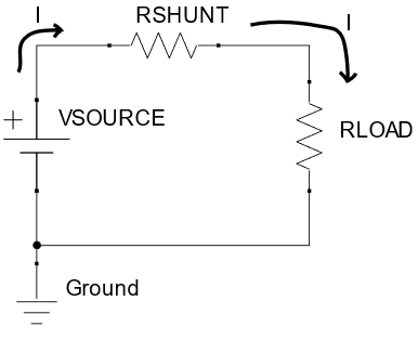
$$ \cfrac{V_{\text{SOURCE}}}{R_{\text{LOAD}}} = I. $$
You may be wondering: what’s the shunt resistor’s role? Because a resistor impedes the flow of charge, there will be a voltage drop between the terminals of a resistor, proportional to the current flowing through it. More accurately, the voltage drop is equal to the current multiplied by the resistance of the shunt.
So, if we know the resistance of the shunt, and the voltage drop across the shunt, then we can change the subject of the equation V = IR to calculate I, which results in
$$ \cfrac{V_{\text{DROP}}}{R_{\text{SHUNT}}} = I. $$
To measure the voltage drop across the resistor, a voltmeter is used, as shown below. For the sake of explanation, assume the voltmeter has infinite resistance.
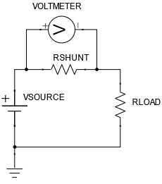
Let us say that the resistance of the shunt is 10 milliohms, and the voltage drop across the shunt is 100 mV. Substituting these values into V/R = I result in I = 10 A. Cool, right?
In my planned circuit, the microSD card is the \(R_{\text{LOAD}}\), and the Voltmeter is an Analog to Digital Converter (with a Current Sense Amplifier beforehand). More about what those two components are and their selection process will be discussed in the next part of this series. Furthermore, the impact of our assumptions regarding the circuit will be explained and how their real effects can be minimized (calibration, etc.).Bye for now, and I’ll see you in the next post!