Hello! In this post I’ll go over the (unsurprisingly) time consuming and complex component selection for Systolic, my 6-lead ECG.
Basic overview of components required
The diagram below should help explain the main elements of the ECG.

The most important parts are the MCU, AFE, regulator, and isolator.
Basic overview of functionality
As you can see in the diagram, the USB connector provides the board with 5 V power, and allows for bi-directional communication with the host device through the differential data pair. The differential data pair and 5 V power are both then isolated. The isolated 5V power enters the dual output regulator, which provides a 3.3 V rail for both the analog and digital domains of the board. This is because both the analog-front-end (AFE) and microcontroller (MCU), thankfully, can work with 3.3 V. I’ll explain more about what the AFE is further into this post. The MCU communicates with the AFE over an SPI bus to get electrode voltages and also for configuration. It is then able to communicate with the host device (e.g. a laptop) over USB, for sending the electrode voltages and also for changing the AFE’s configuration
Components
AFE
The AFE is the device that actually interfaces with the electrodes. It can be thought of as an analog-to-digital converter (ADC) with a lot of extra features, such as current injection for electrode status, input multiplexer, and more. I found through my initial searches that Texas Instruments have a line of AFEs, in their ADS series. The individual AFEs in the ADS family are primarily differentiated by the amount of input channels and ADC resolution (a topic which I go over in this post).
In order to work as a 6-lead ECG, the AFE would need to have at least three input channels. The lowest cost AFE in the family that has three input channels is the ADS1293, which I chose for this project.
It uses an SPI Bus for communicating with the host MCU. It also features something called right-leg-drive (RLD), which is a very important feature that I’ll go over in a future post. This component is in an easy to solder QFN-28 package (with 0.5 mm pin pitch).
MCU
The MCU is going to be the “brains'' of the ECG. It will handle interfacing with the host device and the AFE.
I’ve got experience with MCUs in the STM32 family, so I decided to use one from the same family.
One of the requirements for the STM32 would be that it offers both the SPI and USB communication interface. Finding an STM32 without SPI support would actually be difficult, and finding one with USB support is trivial, thanks to tools like ST’s MCU Finder
Another requirement is that the STM32 has over 128 KB in flash memory. I don’t think the code will ever get to 128 KB, but it’s good to have some breathing room. Lastly, I wanted the STM32 to be from the low-power family (e.g. STM32L0, L1, etc.) so that it wouldn’t be power hungry. With these requirements in mind, I used the aforementioned tool to start searching. Initially, there were 432 MCUs that met the spec, so I removed ones with BGA and WLCSP packages. Doing so reduced the list to 269 MCUs. Looking through the list, I came across the STM32L475RCT6, which met all my requirements.
The MCU is in an easy-ish to solder LQFP-64 package, which was a plus.
With another great tool from ST, STM32CubeMX, it’s easy to configure the pin-muxing and communication interfaces of the MCU. I’ll go over this more in the schematic design post, which is next.
Regulator
A question I had at the start of this project was whether I should use a buck-converter or a linear regulator for producing the two 3.3 V rails from the isolated 5 V input. A buck-converter boasts higher efficiency than a linear regulator, but it typically has higher output noise and voltage ripple. For this device, as it is not battery powered, power efficiency isn’t of great concern. However, noise on the voltage rails is of great concern, as noise on the input voltage of the ADC can introduce noise into the electrode readings. Especially as the ADS1293 uses 24-bit ADCs, there is more sensitivity to noise. This meant that I decided to use a linear regulator for the ECG. To help make the design more simple, I looked for one two-channel regulator, instead of two single-channel regulators.
I came across the TPS7A87 from Texas Instruments, which looked perfect for the job. It has exceptionally low output noise, high input ripple rejection, and good transient response. It is also in an easy to solder QFN-20 package (with 0.5 mm pin pitch). It’s also dual-channel, which makes life easier!
Isolator
An isolator is a critical part of the ECG. It is there to ensure that any dangerous events on the host device, such as the unlikely scenario of mains voltage being shorted to the USB bus, causing harm to the user of the ECG.
In order to isolate the power and USB data, two different components will be used. One will isolate the 5V rail, and the other will, expectedly, isolate the USB data. The USB data isolation is more complex because it is a differential data pair, communication bidirectionally. I chose to use the ADuM4160 from Analog, which manages to isolate the USB data, which requires it being able to sense the direction of data flow. It does this by reading the packets… Wow!
It is able to work with full-speed USB data transfer rates, which is 12 Mbps, but not high-speed (480 Mbps). Not that fast, but suitable for the job. The STM32 doesn’t even support high-speed, so it doesn’t matter anyway. The device is IEC 60601-1 rated, which is the standard for medical devices (which is what I’m trying to abide too wherever possible).
For the 5V power isolation, a more simple, but very large, component is used. This is the NXF1S0505MC-R7 from Murata, which is pending IEC 60601-1 approval. It can output a maximum of 200 mA, which is not much, but enough. It is also very cost friendly, at 4.03 GBP for one. I have to include a picture of this component, because it is one of the coolest I’ve ever seen. It is a mini-PCB!
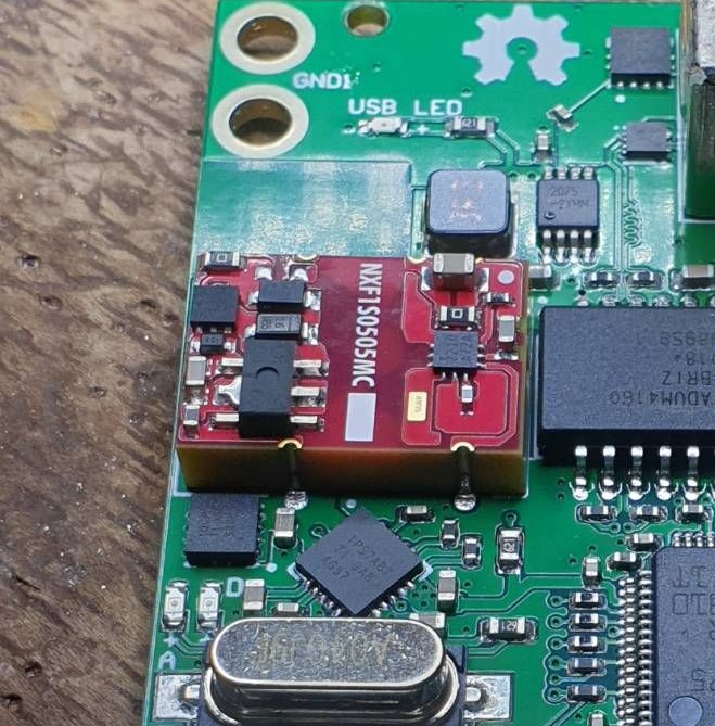
p.s. It’s the massive red thing!
The two aforementioned components will work together, with the NXF1S providing isolated power, and the ADuM allowing isolated USB communication. The ADuM is also powered by the NXF1S.
In the next post, I’ll go over schematic design, which will be very fun!